Multi Robot Simulation progress

Adhoc Simulation

We successfully simulated the Adhoc_communication node as well as the Map Merging node, the result which can be seen in the animated gif at the bottom.

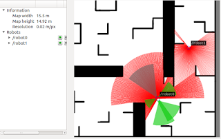
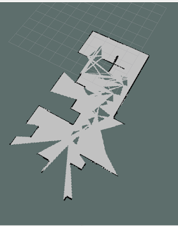
A stage simulation of a small map with 3 robots, two of the robots are publishing individual maps using gmapping the produced maps are then merged in the map_merger node. The merged map is then published and is being represented in RVIZ.


As we can see, the updated global map in RVIZ is refreshing at a relatively slow rate, this is due to the gmapping speed as well as the update speed of the map_merger. Note that the RVIZ representation isn't aligned with the STAGE simulation

This simulation is based on the work of OSLL/multibot (see: https://github.com/OSLL/multibot) a fork of aau-ros/aau_multi_robot project (see: https://github.com/aau-ros/aau_multi_robot)


------------------------------------------------------------------------------------------------


Reading Sensors through ROS and RaspberryPi

Writing The Node:
Nodes are executable pieces of code that run in ROS. This is an example of writing a node for ROS on RaspberryPi (RPi) which continuously reads data from an Input pin on the RPi. In this case the Data is a push button signal.

The first step in writing a ROS Node is a declaration which tells the system to run the script in Python:

#!/usr/bin/env python
 
Then importing the necessary libraries that are required to call certain functions:

import rospy
from std_msgs.msg import String
import RPi.GPIO as GPIO 

Rospy libraries give access to ROS python functions. The "std_msgs.msg" is a library which defines message types which are used in ROS. RPi.GPIO are functions for input/output access on the RaspberryPi.

pub = rospy.Publisher('Pin4Data', String, queue_size=10)
rospy.init_node('Pin4DataReader', anonymous=True)
GPIO.setmode(GPIO.BCM)
GPIO.setup(4,GPIO.IN, pull_up_down=GPIO.PUD_DOWN)

The first line defines the topic name of the node "Pin4Data" which can be subscribed to.
Next the node is initiated with the name "Pin4DataReader".
GPIO.setup sets up reading the button at pin number 4.
The pull_up_down argument controls the state of the internal pull-up/down resistors.

rate = rospy.Rate(10) # 10hz

With the help of the method rate.sleep(), setting up the rate helps defining how fast the node will loop

while not rospy.is_shutdown():
   button_state = "Button State = %s" % GPIO.input(4)
   rospy.loginfo(button_state)
   pub.publish(button_state)
   rate.sleep() 

This loop is the main part of the ROS node, the first while checks if the program should be shutting down (E.G: if Crtl-C is pressed in the command window). While the program shouldn't shut down, it runs the written commands.
The defined string button_state is what we want to publish.
The loop calls pub.publish(String(str)), which publishes the string to the Pin4Data topic.
The loop calls rospy.loginfo(str), which performs triple-duty: the messages get printed to screen, it gets written to the Node's log file, and it gets written to rosout.
The loop calls rate.sleep(), which sleeps long enough to loop the node at the designed rate.

try:
   Pin4DataReader()
except rospy.ROSInterruptException:
   pass

This last bit of code catches a rospy.ROSInterruptException exception, which can be thrown by rospy.sleep() and rospy.Rate.sleep() methods when Ctrl-C is pressed or the node is shutdown. The reason this exception is raised is so that it doesn't accidentally continue executing code after the sleep() function.

The entire code:

#!/usr/bin/env python
 
import rospy
from std_msgs.msg import String
import RPi.GPIO as GPIO
 
pub = rospy.Publisher('Pin4Data', String, queue_size=10)
rospy.init_node('Pin4DataReader', anonymous=True)
GPIO.setmode(GPIO.BCM)
GPIO.setup(4,GPIO.IN, pull_up_down=GPIO.PUD_DOWN)

rate = rospy.Rate(10) # 10hz
while not rospy.is_shutdown():
   button_state = "Button State = %s" % GPIO.input(4)
   rospy.loginfo(button_state)
   pub.publish(button_state)
   rate.sleep() 

try:
   Pin4DataReader()
except rospy.ROSInterruptException:
   pass

------------------------------------------------------------------------------------------------ 
   

Using gmapping with multple robots

What is gmapping ? 
 Gmapping is a ROS packages that allows to create 2-d occupancy grid maps from laser and pose data collected by a mobile robot using SLAM algorithms. This is a very crucial package for our project, and will have to run on each robot.

What do you need to have gmapping running ? 
First of all, you need the hardware, which should be a mobile robot that can provide odometry data and has a horizontally fixed laser sensor. You can also run it with a simulated robot, for example with the stdr 2d environment. as in the example on right.


Running gmapping in a simulation
If you run the stdr simulation, with one robot that has a laser sensor, you can run the following command :
rosrun gmapping slam_gmapping scan:=/robot0/laser_0 _base_frame:="/robot0" map:=/gmapping/map1
this will create a new node called slam_gmapping, which will publish the map on a topic called gmapping/map2. WIth rviz, you can see the map, as in the example below :


If you want to add another gmapping node that would be subscribed to a second robot, you need to launch it with a .launch file, with a different name. Otherwise, ROS will shutdown the nodes if you try running two instances with the same name.
An example of a .launch file for running a second gmapping can be seen below :


as you can see, the name is changed to "slam_gmapping_2" and the parameters are set according to the topics from the second robot. It will publish the map data and map metadata on the topics called
/gmapping/map2 and gmapping/metadata2 .

The whole system architecture should look identical to this one :


In rviz you can visualize both maps in the same environment. However, this will be two completely different unmerged maps. In order to have a unique global map, you need to use map merging packages and algorithms. In a future post we will write more about these kind of packages, together with a small tutorial on how to use them.
https://upload.wikimedia.org/wikipedia/commons/3/38/Flood.gif Wireless Ad Hoc Networks

We are currently looking into different network protocols and systems for the communication between our exploration robots. An ad hoc communication package built by Guenter Cwioro and Torsten Andre is being used by our exploration package. This post explains some background on ad hoc networks and their functionally:

A wireless ad hoc network or WANET is a decentralized type of wireless network. The network is called “ad hoc” from the latin meaning “for this”; “ad hoc” in english signifies a solution designed for a specific problem or task. WANETs don't rely on pre existing infrastructure; instead each node forwards data to other nodes, dynamically switching which nodes route data on basis of network connectivity.

The decentralization of WANET makes them suitable for a variety of applications where central nodes can't be relied on. In our case, it makes swarm robotics possible as each robot needs to communicate with each other, and the amount of robotics isn’t defined.

The benefits of using WANETs include:
    No expensive infrastructure must be installed
    Use of unlicensed frequency spectrum
    Quick distribution of information around sender
    Possibility of Flooding data
    No high speed multimedia exchange protocol

However some aspects need to be considered, such as:
    All network entities may be mobile which requires a very dynamic topology
    Network functions must have high degree of adaptability
    No central entities which cause operation in completely distributed manner

Adhoc_communication package

The package allows the exchange of data over several roscores by wrapping and transmitting the data to the destination and publishing the data on a predefined topic at the destination host. The routing is accomplished by using the hostname of the robots.

Package summary: http://wiki.ros.org/adhoc_communication
Source git: https://github.com/aau-ros/aau_multi_robot.git

The adhoc_communication node implements three types of routing:

Unicast Routing, one to one communication which transmits data from one robot to the other.
Multicast Routing, one to many communication which transmits from one robot to many robots. Each robot already has a multicast that can be subscribed to other robots
Broadcast Routing will be received and published by all robots (Flooding)
  
The adhoc_communication node, although built to send a majority of ROS messages isn’t fully integrated. Instead messages can be serialized at the sender and then deserialized at the receiving robots.

------------------------------------------------------------------------------------------------

STDR Simulator


STDR Simulator (2D multiple robot simulator)
Simple Two Dimentional Robot Simulator (STDR Simulator) is a 2-D multi-robot Unix simulator (Figure 1). Its goals are:

Easy multi-robot 2-D simulation
STDR Simulator's goal is not to be the most realistic simulator, or the one with the most functionalities. Our intention is to make a single robot's, or a swarm's simulation as simple as possible, by minimizing the needed actions the researcher has to perform to start his/hers experiment. In addition, STDR can function with or without a graphical environment, which allows for experiments to take place even using ssh connections.

To be ROS compliant
STDR Simulator is created in way that makes it totally ROS compliant. Every robot and sensor emits a ROS transformation (tf) and all the measurements are published in ROS topics. In that way, STDR uses all ROS advantages, aiming at easy usage with the world's most state-of-the-art robotic framework. The ROS compliance also suggests that the Graphical User Interface and the STDR Server can be executed in different machines, as well as that STDR can work together with ROS Rviz.

Instruction (for Ubuntu Indigo)

1. Download:
sudo apt-get install ros-indigo-stdr-simulator

2. Run STDR Simulator:
roslaunch stdr_launchers server_with_map_and_gui_plus_robot.launch

3. Run Rviz for visualization:
roslaunch stdr_launchers rviz.launch

4. Load a map:
alt text

5. Load a robot in a map:
alt text

6. Open the robot creator:
alt text

7. Add sensors / Load sensors:
alt text

8. Manipulate sensors:
alt text

9. Save / Load robot:
alt text

10. Control the robots with your keyboard:

10.1. Install:
sudo apt-get install ros-indigo-teleop-twist-keyboard

10.2. Launch keyboard control:
rosrun teleop_twist_keyboard teleop_twist_keyboard.py cmd_vel:=robot0/cmd_vel
> You can choose the robot you want to control, by changing the robot0/cmd_vel to robot1/cmd_vel and so further on.


11. Read sensor:

11.1. List of active sensors:
rostopic list

11.2. Read for example the laser sensor of robot 0
rostopic echo /robot0/laser_1

Odometry

What is odometry?
Odometry is the use of data from motion sensors to estimate change in position over time. Odometry is used by some robots, whether they be legged or wheeled, to estimate (not determine) their position relative to a starting location. This method is sensitive to errors due to the integration of velocity measurements over time to give position estimates. Rapid and accurate data collection, equipment calibration, and processing are required in most cases for odometry to be used effectively.

What does a robot need for odometry?

Rotary encoders are needed to measure the movements of rotary joints (e.g. wheels). Higher accuracy is achieved with higher resolution. The resolution is measured in degrees.
Linear encoders are needed to measure the movement of prismatic joints (e.g. linear actuator). Higher accuracy is achieved with higher resolution. The resolution is measured in meters.
Processing unit to read encoder data, save position data and perform basic trigonometric calculations.

Odometry in ROS

The tutorial in the link below provides an example of publishing odometry information for the navigation stack. It covers both publishing the nav_msgs/Odometry message over ROS, and a transform from a "odom" coordinate frame to a "base_link" coordinate frame over tf.
http://wiki.ros.org/navigation/Tutorials/RobotSetup/Odom
The navigation stack uses tf to determine the robot's location in the world and relate sensor data to a static map. However, tf does not provide any information about the velocity of the robot. Because of this, the navigation stack requires that any odometry source publish both a transform and a nav_msgs/Odometry message over ROS that contains velocity information.

Calculation examples using rotary encoders on wheels

Assumptions:

  • The robot has two wheels, each equipped with a rotary encoder (other wheels may be used for balance)
  • The wheels are parallel to each other and equidistant to the centre of the robot

A sketch of these assumptions can is presented in figure 1. The gray area is the robot base, whereas the black rectangles provide a top view of the wheels.
Figure 1 Topview of the robot
For each ‘tick’ of the encoder, a binary value is increased by one. The new position and orientation of the robot depend on the increase in ticks since the last known position/orientation,

Where tick is the increase in delta ticks, tick' is the current number of ticks and tick is the previous number of ticks.
One ‘tick’ equals a rotation in degrees, depending on the encoder resolution. To determine the distance traveled by one wheel (D), one has to multiply the circumference of that wheel (C) with the increase in ticks and the resolution of the encoder (R) and divide it by 360 degrees, equation 2.

figure 2
By calculating the distance each of the two wheels have traveled and using the assumptions above, the distance traveled by the centre of the robot is easily calculated, equation 3.

Where Dc is the centre of the robot, Dl and Dr are respectively the left and right wheel of the robot. Figure 2 gives an example.

                                                             
Equations 4, 5 and 6 are used to respectively calculate the new x-position, y-position and orientation (phi), by adding the previous position/orientation to the change in position/orientation.
The change in x and y direction is calculated by multiplying the distance traveled by the base of the robot with respectively the cosine or sine of the orientation of the robot.
The change in orientation is calculated by the difference in distance traveled by each wheel, divided by the distance between the wheels.


Restrictions
Odometry is inaccurate at medium and long range distances.
When using wheel encoders, inaccuracy occurs when wheels drift (spinning while not moving forward) or when driving over bumps on the floor.
Solution
Use a gyroscope to measure the angular acceleration. By integrating the angular velocity or angle can be calculated. In this way, the gyroscope can be used to check for any deviations on the angle of the robot.

------------------------------------------------------------------------------------------------

Pathfinding Algorithms

Pathfinding 

Pathfinding is the plotting and solving of the shortest route from one point to another.
There are many different pathfinding algorithms, most of them based on Dijkstra's algorithm,  which finds the shortest paths between nodes in a graph.

Basic Pathfinding using Breadth-first search

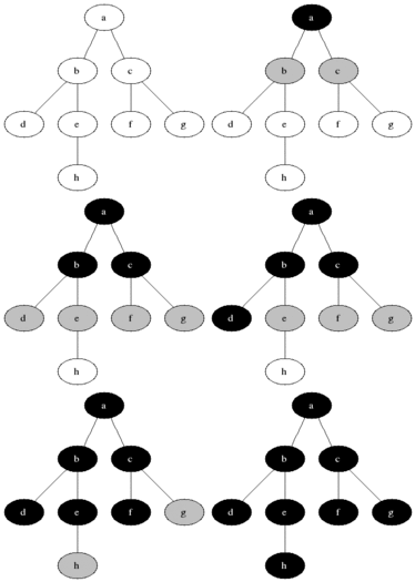
One of the most basic pathfinding algorithms would be the Breadth-first search method. An iterative system which starts either at the root node or an arbitrary node of the tree/graph and explores the neighbouring nodes, then moves on to the next level and recycles this process.

The Pseudocode for this algorithm:
1     for each node n in Graph:            
2         n.distance = INFINITY        
3         n.parent = NIL
4 
5     create empty queue Q      
6 
7     root.distance = 0
8     Q.enqueue(root)                      
9 
10     while Q is not empty:        
11     
12         current = Q.dequeue()
13     
14         for each node n that is adjacent to current:
15             if n.distance == INFINITY:
16                 n.distance = current.distance + 1
17                 n.parent = current
18                 Q.enqueue(n)

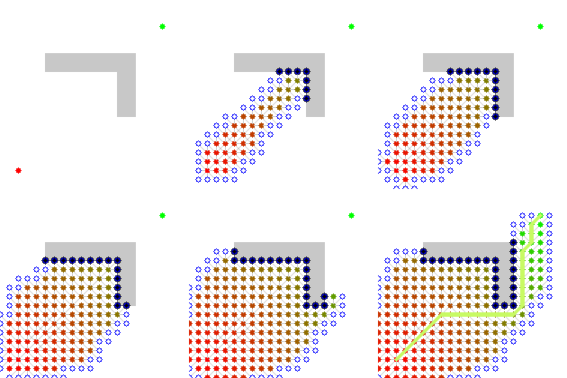
The problem with an algorithm such as Breadth-first is that it's slow and has to iteratively go through all nodes, instead an algorithm that explores the graph would reach its destination sooner.

Dijkstra's algorithm

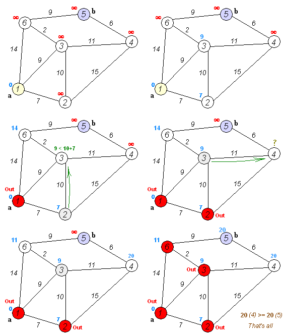
https://upload.wikimedia.org/wikipedia/commons/5/57/Dijkstra_Animation.gifSimilarly to the Breadth-first algorithm, Dijkstra's concept was to starts at the root node and explores its neighbours, however it chooses undiscovered nodes with the lowest distance from the previous node and calculates the distance through it and its unvisited neighbours, then updates the distance if it's smaller and keeps it unused if it's greater.

To build an algorithm around this concept we use a similar approach to the previous pseudocode.
Each node has an infinite distance from the root node, and the root node has distance 0.
The root node is the current node, and all other nodes are in a set of "undiscovered nodes"
Then start iterating for the current node, calculate the distance to all its unvisited neighbours and compare the newly calculated distances to the currently assigned value, if the new distance is smaller, replace, if not continue.
Once the destination has been reached, stop the algorithm.

To put this in Pseudocode:

 1  function Dijkstra(Graph, root):
 2
 3      create empty queue Q
 4
 5      for each vertex n in Graph:             
 6          dist[n] = INFINITY                  
 7          prev[n] = NIL
 8          add n to Q                          
 9
10      dist[root] = 0                        
11      
12      while Q is not empty:
13          u = node in Q with min dist[u]    
14          remove u from Q 
15          
16          for each neighbor n of u:           
17              alt = dist[u] + length(u, n)
18              if alt < dist[n]:               
19                  dist[n] = alt 
20                  prev[n] = u 
21
22      return dist[], prev[]

A* Algorithm

The A* (pronounced A Star) algorithm is another algorithm based off of Dijkstra's algorithm. It's used in multiple pathfinding systems. It performs better then Dijkstra's algorithm, although is similar in how it works.


https://upload.wikimedia.org/wikipedia/commons/2/23/Dijkstras_progress_animation.gif


 This animation shows Dijkstra's algorithm reaching it's goal, as we can see, it checks all neighbouring nodes before reaching its destination.


https://upload.wikimedia.org/wikipedia/commons/5/5d/Astar_progress_animation.gif


In contrast, A* tries to directly reach it's goal by using a priority queue system. A priority queue is known as the "Open Set". At each step of the algorithm, the node with the lowest cost and estimated cost value is removed from the queue, the cost values of its neighbours are updated accordingly, these neighbours are added to the queue.


------------------------------------------------------------------------------------------------

ROS packages for multi-robot exploration

Since ROS is an open source operating system, there are a lot of packages being developed every day. Our aim is to use as many available packages as possible and not reinvent the something that was created already. The resources that we looked into are map merging, exploration movement algorithms and multi-robot publisher. 
Luckily for us, there are already such packages available, which are: 
- explore_multirobot http://wiki.ros.org/explore_multirobot 
- map_merging http://wiki.ros.org/map_merger
- tf_splitter http://wiki.ros.org/tf_splitter
- pose_publisher http://wiki.ros.org/pose_publisher


Map_merger
This is a package that will allow us to merge multiple maps; It can distribute the data live and create a live global map. In the example below you can see a map created by two robots:
The map_merger node offers the following features:
-  Keeping track of changes in the local map and automatically distributes them in the network using the Ad hoc Communication package.
 - Attempting to merge local maps received by other robots by computing a transformation between the coordinate systems of the robots.
 - Allowing other packages to transform coordinates between different coordinate systems of multiple robots.
-  Maps are merged pair-wise.
-  Automatically attempts to determine the transformation between coordinate systems and attempts to continuously improve the transformation based on a quality metric.
Upon updates of the local map only parts of the map that have changed are distributed minimizing transmission overhead.
Storage of map updates sent to other robots for retransmissions.
-  Keeps track of received map updates distributed by other robots. If missing map updates are detected, the map_merger node automatically requests retransmission of the missing updates.

In the picture below you can see an example of the nodes that participate in map merging:

Explore_multirobot
This package is responsible for movement decision of multiple robots. It can subscribe to additional topics such as map and goal. This package can work with different type of robots, and different type of odometry data.
Tf_splitter
The tf_splitter package contains a ROS node that decomposes the /tf topic into multiple ones according to the number of robots. This package can be used in multi-robot systems to alleviate the network traffic load.
More information and documentation can be found on the link provided in the beginning of this post

------------------------------------------------------------------------------------------------ 

SLAM

What is SLAM?

Simultaneous localization and mapping. Slam is the process of constructing or updating a map of an unknownenvironment while simultaneously keeping track of an agent’s location within it, for example a robot. The maincomponents of a SLAM process are the sensing, processing of data, visualization of data, and decision making.

What does a robot need for SLAM?

The first thing that is needed in a robot in order to be able to map the environment are sensors which can be ultrasonor,laser or any type of depth camera. A locomotion system is also needed in order to be able to map a bigger area from different angles and perspectives. The last thing is a processing unit, which should be a powerful processor, able to run an operating system, like ROS. An overview of the slam process can be seen in the figure on the left:


SLAM in ROS


Ros is one of the most powerful software/firmware tools for robots nowadays. It already contains a lot of implemented SLAM tools and algorithms which is universal for any shape of robot with a wide range of sensor types. It can easily combine data from different sources, and put it in the same software 3d environment. For example, in the image on the right you can see a ROS robot mapping a room based on laser sensors and a Kinect camera: 


SLAM algorithms

SLAM is not based on a unique formula or general rule. However, there are some key elements that are present in any type of SLAM algorithms. For example, Landmarks are one of these elements. Landmarks are features which can easily be re-observed and distinguished from the environment. These are used by the robot to find out where it is (to localize itself). One way to imagine how this works for the robot is to picture yourself blindfolded. If you move around blindfolded in a house you may reach out and touch objects or hug walls so that you don’t get lost. Another important element is the approximation of the incoming data. Sensors cannot be trusted 100%, there are lot of errors and unprecise values; that’s why a lot of approximation algorithms are needed. For example an array of points from a laser scan , can be approximated to a line, which can be a wall or an obstacle. In the image below, there is a good example of this type of approximation:


SLAM in cooperative robotics

Also called C-SLAM; This is a new technology which started developing in 2015. Most of the research and papers about this topic are not open for the general public, or have to be paid. The main idea of C-SLAM is to combine mapping data from multiple sources. The robots should share the landmarks, and also the information about their current position, in such a way that it can be defined a difference between an obstacle and another robot.
Merging of maps can be done in an environment like rViz using ROS. An example of map merging can be seen on the left:


In order to merge the maps, there should be common landmarks in order to define the merging points. That means that the robots should meet at least once during the whole process of mapping. In order to make it easier for the position calibration, the robots should start mapping from the same place, which will be used as a reference point for the general map. An important thing is the efficiency of movement of the robots. The robots should avoid mapping the same landmarks and taking the same directions.
However, a thing to keep in mind is that robots should easily detect each other. A solution to that would be placing markers with different ids on each robot, like in the picture on the right: 

------------------------------------------------------------------------------------------------